
Power transformer monitoring: not just data collection, but a decision-making system
2026-01-09
content
- From temperature to gases: what's really important to track
- ?Iron? and “software”: how not to drown in a sea of offers
- Partial discharges: subtle diagnostics that require experience
- Practice and economics: when monitoring pays off and when it doesn’t
- Mistakes and conclusions: what field work taught me
When they talk aboutmonitoring of power transformers, many immediately imagine graphs on the screen and sensors that “measure everything themselves?” This, of course, is the basis, but the biggest mistake is to think that you bought a set of equipment, installed it, and now it works for you. In fact, this is just the beginning of the story. The main work is interpreting data, building cause-and-effect relationships, and, most difficult, determining which deviations are truly critical and which ones can simply be addressed for now. I often see how substations have an expensive system, but they look at it once a quarter, and only then to generate a report. Then they are surprised when the transformer ?suddenly? fails. Monitoring is a daily routine, like checking the blood pressure of a hypertensive patient. The readings may be normal, but the trend is already alarming.
From temperature to gases: what's really important to track
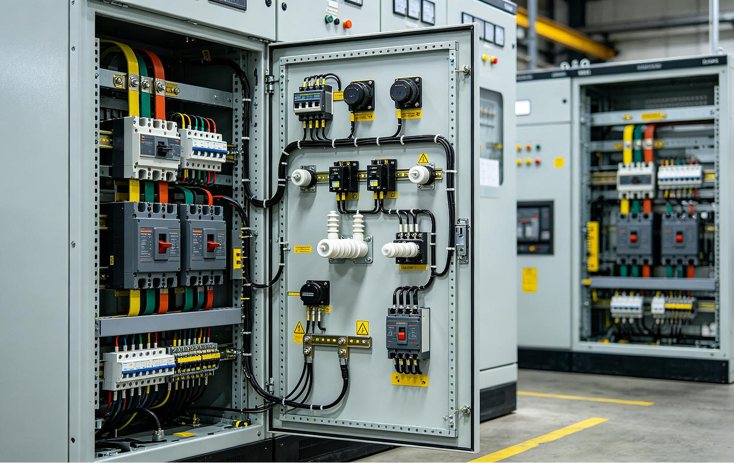
Let's start with the classics - temperature, because the correct choice of measurement points is an important part of monitoring power transformers. It is not enough to simply measure the temperature of the top cover. The temperature gradients between the windings, the temperature of the active part and the values at the hot spots of the equipment are critical. We had a case at one of the city substations: sensors installed on the transformer housing showed a stable 65°C, but differential analysis of periodic thermal imaging surveys (which were not carried out online) revealed local overheating in the bus contact area. Upon inspection, it turned out that the reason was a loose contact connection. The online monitoring system did not detect this because the sensors were mounted according to a standard layout that did not take into account the characteristics of a particular object. After this, the sensor placement scheme had to be modified to improve diagnostic efficiency.
The next layer is gas protection and chromatographic analysis. DGA (Dissolved Gas Analysis) is a must have for oil transformers. But there are plenty of pitfalls here too. You cannot blindly trust a single excess of hydrogen or methane. You need to look at the key ratios: ratios C2H2/C2H4, CH4/H2, C2H4/C2H6. Based on them, a classification of defects according to Rogers or Dornenburg is built. Often laboratories simply send a table with concentrations, without interpretation. And operational personnel do not always know how to read it. For our clients from energy companies, we always make a transformer card with a test history and trend graphs - this is the only way to see the dynamics. A sharp rise in ethylene (C2H4) is a sure sign of thermal decomposition of the oil at temperatures above 700°C, often associated with poor contact. And acetylene (C2H2) is already a discharge.
And the third underestimated parameter is moisture in the monitoring of power transformers. Moisture in oil and paper insulation is the main enemy: it reduces the electrical strength and accelerates aging. Online humidity sensors are capricious and require calibration. Monitoring the dew point in the expander is a good proxy. It is not the absolute value that is important, but the rate of change: a rapid increase signals leakage or cellulose decomposition.
?Iron? and “software”: how not to drown in a sea of offers
The market is flooded with systems for monitoring power transformers: from simple telemetry modules to complex AI platforms. The choice depends on the task. For critical objects - central substations, energy-intensive industries - an integrated system is needed that combines data from relay protection, cooling, gas analysis and partial discharges. For example, we sometimes select solutions from partners, such as Qualitrol or Weidmann products, adapting them to Russian regulations and operating conditions.
But for distribution networks 6-10/0.4 kV there is no point in overpaying often. Here, point solutions are more effective: temperature and load monitoring with data transmission via GSM. The main thing is that the device is reliable and “survives” our frosts and voltage drops in operational current circuits. Many times I have seen how it “flies” firmware or the power supply fails. So now we're inWenzhou Qiaonasen Electrical Equipment Co.,LtdWhen selecting equipment for clients, we always look not at beautiful brochures, but at test reports in climate chambers and real reviews from similar facilities. Our websitehttps://www.qnasen.ruAlthough we represent a company specializing in solutions for the transmission and distribution of high and low voltage, we understand that the monitoring system is not a separate product, but part of the overall infrastructure. It needs to be interfaced with existing SCADA and automated process control systems.
The biggest headache is integrating data from different systems, especially if the equipment is of different years of manufacture. Old transformers may have analog sensors, new ones may have digital outputs. You have to use gateways and converters. And here a problem often arises with exchange protocols. IEC 61850 is good, but many sites still use Modbus RTU. Our company’s specialists often have to act as such “integrators”, selecting compatible equipment and helping to set up data exchange.
Partial discharges: subtle diagnostics that require experience
Partial discharge (PD) monitoring is top-notch. Expensive and difficult to set up, but sometimes this is the only way to catch a developing defect in insulation at an early stage. It is important to understand that recording the fact of a CR is not a death sentence. It is necessary to determine the type of discharge: internal, surface, corona. To do this, analyze the pulse shape, phase distribution, and connection with the network voltage.
We somehow installed a permanent PD monitoring system on a 110 kV transformer. The background was elevated, but stable. Six months later, characteristic clusters of impulses appeared in a certain voltage phase. The analysis showed signs of surface discharges along the barrier. During an internal inspection (when they were taking it out for repairs), they found traces of tracking on the surface of the solid insulation - moisture ingress through a leaky seal. If it were not for constant monitoring, the defect would develop further, up to a breakdown.
But here there are nuances for monitoring power transformers. Strong interference from thyristor drives or neighboring equipment can completely “clog” the useful signal. High-frequency current transformers (HFCTs) must be installed carefully and complex filtering algorithms must be used. This is not a “box” solution - each case is individual.
Practice and economics: when monitoring pays off and when it doesn’t
Implementation of the system is a capital expense. To justify them, we do not count in words. The main savings are the prevention of emergency downtime and costly repairs. The cost of replacing or overhauling a power transformer is several times higher than the cost of the monitoring system. But you need to calculate exactly: what is the damage from the undersupply of energy, what are the fines, the cost of the emergency crew, logistics.
The second point is optimization of maintenance. Transition from routine maintenance “according to the calendar?” to maintenance based on actual condition (TOFS). This saves on materials, labor costs and, importantly, on unnecessary equipment shutdowns. For example, if the gas and moisture analysis is stable, it is safe to extend the oil cleaning service interval.
And the third, less obvious point is extending the service life. Competentmonitoring of power transformersallows you to control the load without allowing critical overheating, and thereby slow down the aging of the insulation. This is a direct deferment of capital investments in new equipment. In our projects, we always focus the customer’s attention on this: this is not an expense, it is an investment in reliability and deferment of large costs.
Mistakes and conclusions: what field work taught me
Not everything went smoothly in practice. There was a project where we put vibration sensors on a transformer tank, hoping to improve the qualitymonitoring of power transformersand diagnose the condition of the magnetic circuit in the early stages. The readings from the devices turned out to be strange and unstable - they were highly dependent on the operation of the cooling fans and even on the direction of the wind outside (the substation was of an open type). In the end, it was not possible to extract useful diagnostic information, and the funds for the purchase and installation of sensors were wasted. The conclusion from this situation is simple: not all diagnostic methods are universal. Vibration analysis works great for rotating machines, but for transformers its application is very limited and requires the creation of ideal environmental conditions, which can rarely be achieved in real objects.
It's a different story with data transfer. We saved on the communication channel and installed the radio modem in an area with difficult terrain. Packet losses reached 40%. The data came with gaps, the trends were built crookedly. We had to redo it and lay optical fiber. Now this is an ironclad rule: first evaluate the reliability of the communication channel, and then choose hardware.
And the main conclusion that is perhaps worth making is that the monitoring system does not make decisions. She just gives information. The key link is a person, an engineer, who looks at the summary data, knows the history of a particular transformer, its operating conditions and can make a balanced conclusion. Automatic systems for diagnosing and generating conclusions are good, but they should only be an assistant and not a replacement for an expert. Therefore, introducingmonitoring of power transformers, it is necessary to simultaneously train staff, explain the physics of processes, and not just show where the “generate report” button is on the screen. Without this, any system, even the most expensive, turns into a useless toy.