
Dry-type transformer adjustment: what is often overlooked
2026-01-09
content
When they talk aboutdry transformer adjustment, many people immediately imagine the voltage and turns. But in practice, especially with modern models, everything depends not so much on the mechanics of switching branches itself, but on understanding why this is done under specific operating conditions. A common mistake is to go to the switch without a full analysis of the load and temperature conditions. I myself saw how they tried to “tighten up” at one of the objects. voltage under load, without taking into account that the transformer is already operating at the upper temperature limit. As a result, the parameters do not reach the nominal value, but local overheating and subsequent shutdown by the protection. So adjustment is not a separate operation, but part of the overall system setup.
Basic principle and where the difficulties lie
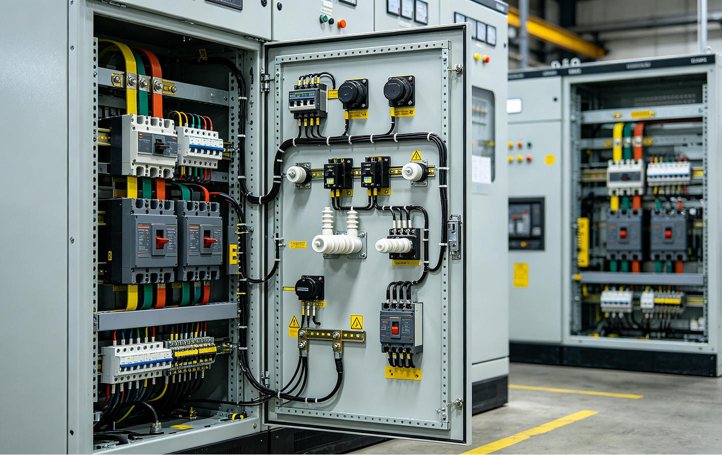
If we discard the theory, then the essence of the adjustment is changing the transformation ratio. In dry-type transformers this is usually done through tap switching on the HV winding. It would seem that everything is simple: turn off the power, move the jumper, check. But the difficulty starts with access. In compact cases, especially from imported manufacturers or those who focus on a dense layout, getting to the terminal block of the adjusting taps is another task. Sometimes it is necessary to dismantle part of the casings, which already risks the integrity of the insulation.
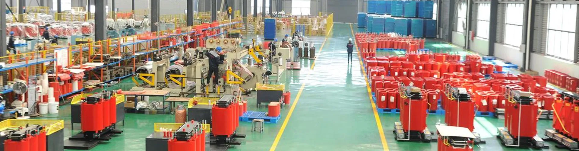
Another point is labeling. It should be perfectly readable. In practice, it happens that the tags are erased or, worse, do not correspond to the real diagram. Once I encountered a transformer where the nameplate indicated ±5%, but in fact the taps gave steps of 2.5%. I had to check the passport, which, fortunately, was on the manufacturer’s website -Wenzhou Qiaonasen Electrical Equipment Co.,Ltd. By the way, their resource (https://www.www.qnasen.ru) often helps out when documentation from a site is lost - there you can find diagrams and manuals for your products. The company, let me remind you, specializes in solutions for the transmission and distribution of high and low voltage, so their documentation is usually in order.
And the main difficulty is assessing the need for adjustment. You can’t just go and set the maximum voltage because “the network is down.” You need to look at the load graph, harmonic distortion (especially if there are non-linear consumers nearby), and take into account the transformer’s own losses after switching. Sometimes it is more stable to leave it as is, but compensate for the problem in another part of the chain.
Tools and preparation: what is better not to start without?
In addition to the standard set of keys and indicators, you definitely need an accurate multimeter with verification and, critically, a megger. Measuring the insulation of windings before and after switching is a sacred matter. Many people neglect, they say, “dry?” same, not oily. But dust, condensation, microcracks in the insulation after mechanical impact - all this can come out later.
Be sure to study the passport of a specific transformer. For example, for some models, switching involves not just changing the jumper, but physically rearranging the copper bars between different pairs of contacts. If you do this in the wrong sequence, you can get an interturn short circuit. Here again it helps if the manufacturer is the sameQnasen, gives not just general instructions, but detailed diagrams for each power. On their website in the support section there are often such specific files.
Thermography is ideal for preparation. You warm up the transformer under operating load, look with a thermal imager at the area of the control taps and nearby connections. If there is abnormal heating in this area before work begins, this is a red flag. Perhaps the problem is not in the transformation ratio, but in a loose contact on the switch itself. Then adjusting the voltage will only make the situation worse.
Switching process: steps and subjective observations
The first rule is complete shutdown and posting prohibiting posters. Even if at the facility they say “everything is turned off here?”. I check the absence of voltage at all inputs myself. After this, I give the transformer time to cool down if it was working. Warm insulation is more plastic, but also more vulnerable to mechanical stress.
Having removed the protective covers, the first thing I do is photograph the original position of all the jumpers. It is not enough to trust the diagram - you need to link it to a real device. Then a visual inspection. I am looking for signs of overheating (darkening of insulation, melting of plastic), oxides on copper surfaces. If the contacts are in good condition, the work goes faster.
The switch itself. The important thing here is not to put in unnecessary effort. Threaded connections on the contacts must be tightened with a torque wrench according to the torque specified in the data sheet. If it is not there, I am guided by common sense and feeling: it must be tightened securely, but without fanaticism, so as not to break the thread or deform the copper bar. After tightening each contact, I usually run a brush with alcohol over it several times to remove any possible contaminants.
An often forgotten step is checking the travel and locking of the switch (if there is one, and not just a block). It should clearly move into positions corresponding to the marks, without intermediate positions or unnecessary play.
Commissioning and possible “surprises”
After assembly, but before applying voltage, use the megger again. The insulation resistance should not be lower than the rated value, or better - the same as before the work, or higher. If there is a fall, I look for the reason: perhaps I forgot to remove metal shavings or overtightened the connection, which led to a microcrack.
Voltage supply - first at idle. I measure the output voltage on each phase. It must correspond to the calculated one taking into account the new outlet. But here’s a nuance: due to asymmetry in the network, there may be slight discrepancies at different phases. It's normal if it's within 1-2%. If more, this is a reason to think about problems in the incoming line, and not in the transformer.
Afterdry transformer adjustmentI give the load, if possible in steps. I monitor not only the voltage, but also the sound. After adjustment, the dry transformer should not begin to hum more strongly or differently. A new, even hum - yes. The appearance of a crackling sound or uneven “singing” - no, this may indicate poor contact or weakening of the winding compression.
The most common ?surprise? - when after all the work the output voltage has not changed as expected. This usually means that the problem was not in the transformation ratio, but, for example, in increased contact resistance on the main input busbars or in the cable line itself. We have to expand the search area. This is exactly what happened once - I spent half a day making adjustments, but the problem turned out to be an old, oxidized connection in the switchgear cell ten meters from the transformer.
Prevention and Long-Term Considerations
Adjustment is not a one-time event. If a facility has seasonal or daily load fluctuations, seasonal switching may be required. This should be reflected in the service regulations. I always recommend that clients keep a simple log: date, tap positions, measured input and output voltages under load, winding temperatures. A year later the picture becomes very clear.
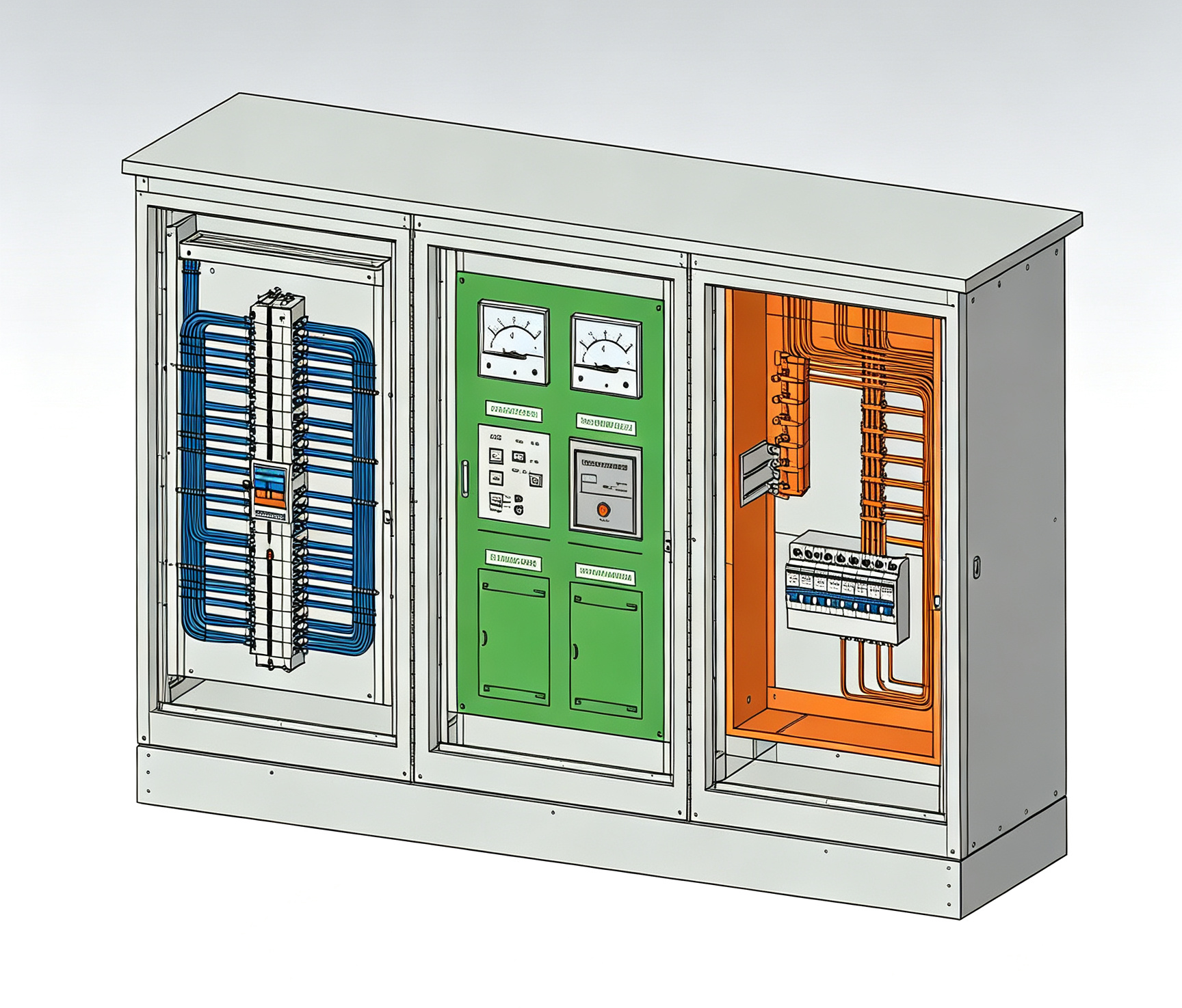
It is also worth paying attention to modern monitoring systems. Some manufacturers, includingWenzhou Qiaonasen Electrical Equipment Co.,Ltd, offer additional cabinets with intelligent metering for their transformers. They allow you to monitor parameters in real time and even simulate the effect of changing the tap, without physical intervention. For critical facilities, it's worth it.
Ultimately competentdry transformer adjustment- this is not about twisting screws. This is about system analysis, accuracy and understanding of how this node fits into the overall network. Blindly following instructions without taking into account specific conditions is a sure way to imaginary successes and real problems in the future. It is better to spend an extra hour on diagnostics before starting work than a week on eliminating the consequences after.